Music machine

Read more

The Challenge

Create a music machine!

Solution

I integrating an Arduino-based control interface with a processing-based sound system creating a dum kit.

Role

Engineer

Industry

Electronics

Timeline

March 2025

Tools

Arduino

Open processing

02. Design challenge

How might I design an interactive music-making system that seamlessly integrates physical hardware and software?

03. Understanding currents
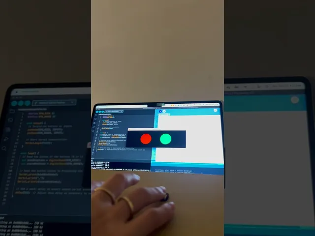
The final outcome

I coded two drums: the snare is in red, and the kick drum is in green. I also created a visualizer effect with floating circles around the canvas at the beginning of the sound. As the musician plays, the two circles expand when the drums are being pressed.

04. Converting data

Arduino code

I wrote this code to create a simple way of reading and sending the status of two buttons—one for a kick and one for a snare—using an Arduino. The goal was to design a basic input system where pressing the buttons would send a signal to a computer, allowing me to use the button states in a program like Processing. By checking whether each button is pressed or not, and sending that information over serial communication, I can create a drum pad-like interface that can easily be expanded or integrated into other projects. The small delay ensures smooth data transfer without overwhelming the system with too much information at once.

#define BTN_KICK 13
#define BTN_SNARE 12

void setup() {
  // Initialize buttons as inputs
  pinMode(BTN_KICK, INPUT);
  pinMode(BTN_SNARE, INPUT);

  // Start serial communication
  Serial.begin(9600);
}

void loop() {
  // Read the states of the buttons (0 or 1)
  int kickBtnState = digitalRead(BTN_KICK);
  int snareBtnState = digitalRead(BTN_SNARE);

  // Send the button states to Processing via serial communication
  Serial.print(kickBtnState);
  Serial.print(',');
  Serial.println(snareBtnState);

  // Add a small delay to ensure smooth serial communication
  delay(50);  // Adjust this delay as necessary to avoid flooding serial data
}

05. C++

Open processing code

I coded this to create a simple way to interact with physical buttons and send their status to a computer. The goal was to design a basic input system where pressing the buttons could trigger actions in a program like Processing. By using the Arduino to read the button states and send them via serial communication, I can integrate simple physical controls into digital projects, such as building a DIY drum pad or interactive interface. The small delay between readings ensures the data is sent smoothly, without overloading the system, making it easy to expand and refine the project as needed.

import processing.serial.*;
import processing.sound.*;
SoundFile kickDrum;

Serial myConnection;
String incomingData = "";
float pot = 0;
float photo = 0;
float button = 0;

void setup(){
  size(600, 600);
  printArray(Serial.list());  // List all available ports to verify the correct one
  
  //kick drum:
  kickDrum = new SoundFile(this, "BT7AADA.WAV");
  
  // Open serial connection; adjust index if needed
  myConnection = new Serial(this, Serial.list()[3], 9600);
  myConnection.bufferUntil('\n');  // Buffer until newline character
}

// Change Color Visual
void draw() {
  // Change background based on button state
  if (button > 0){
    background(255);  // White when button is pressed
    kickDrum.play();
  } else {
    background(0);  // Black otherwise
  }
  
  // Use photoresistor value to influence color of the square
  fill(photo, 255 - photo, 100 + photo); // Color changes with light sensor
  
  // Draw square shape using pot as the "size"
  float halfSize = pot / 2;
  rectMode(CENTER);  // Draw rectangle from the center
  rect(width / 2, height / 2, pot, pot);  // Square with side length 'pot'
}

void serialEvent(Serial conn){
  incomingData = conn.readString();  // Read the incoming serial data
  String[] values = split(trim(incomingData), ",");  // Split the data
  println(values);  // Print received values for debugging
  
  // Map the received values for use in Processing
  pot = map(float(values[0]), 0, 4095, 50, width); // Potentiometer to size
  photo = map(float(values[1]), 0, 4095, 0, 255);  // Photoresistor to color
  button = float(values[2]);  // Button state
  
  printArray(values);  // For debugging, print received values
}

03. p5.js

The hardware

The resistor is connected to the button to complete the circuit. When the button is not being pressed, there is still a connection to the ground through the resistor. Buttons are bridging gap on the breadboard. One leg of the button is connected to a digital pin on the Arduino, and the other leg is connected to the power.